The OddBot is a little mecanum wheeled omnidirectional robot specifically designed to be 3D printable on almost any 3D printer, ranging from the Up! printer to high end laser sintering systems.
A mecanum wheel, invented by Swedish engineer Bengt Ilon in 1973, is a special wheel, with angled rollers around its periphery, that allows a vehicle to move sideways without needing to change the angle of it's wheels. If the front wheel rotates in one direction and the rear wheel rotates in the opposite direction, you get a sideways motion.
This particular incarnation of a baby mecanum wheeled robot was inspired by the work of John Chan (aka Madox) who first posted his work on the Up! forum. You can see his excellent work atwww.madox.net.
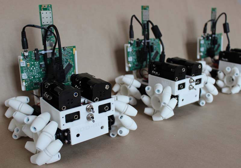
This project is intended as an educational 'open-source' project in which users are welcome to download the files, build their own and modify it to suit their needs.
OddBot Assembly Instructions
Mechanical assembly
Step 1: 3D print all the components. For this particular version, you need one chassis, 2 right hand hubs, 2 left and hubs, 28 round hole rollers and 28 hex hole rollers. The parts can be printed on almost any 3D printer though, obviously, the better the quality of the parts, the better the robot works. We've obtained the best results with laser sintered (SLS) parts.
The battery holder and infocast stand are optional, and depend on which micro-controller and batteries you intend to use.
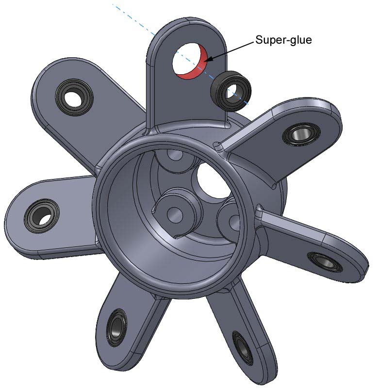
Step 2: Insert the ball bearings into the wheel hubs. Depending on which 3D printing process you are using, the bearings may be a tight fit (which is good, so long as it is not too tight) or a loose fit. If the fit is loose, glue the ball bearings into the wheel hubs, using super-glue as shown in the picture below.
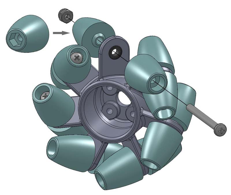
Step 3: Attach the rollers to the wheel. Use M3 x 30 screws and nylock nuts to attach the rollers to the hub. The easiest way to do this is to, first, push the nylock nut into the hex shaped holes on the rollers, then insert the screw into the roller with the round hole, and screw the 2 together.
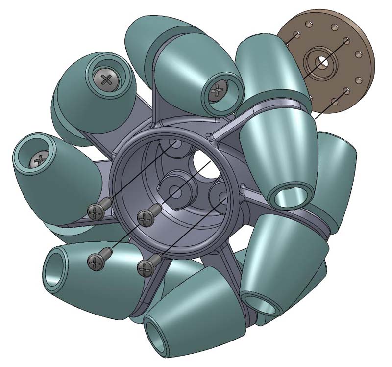
Step 3: Screw the servo horn (included with the servo motors) onto the hub using four M2 x 8 self-tapping screws. Do not overtighten the screws!
Step 4: Screw the servo motors to the OddBot chassis using the screws, eyelets and rubber spacer that are included with the motors.
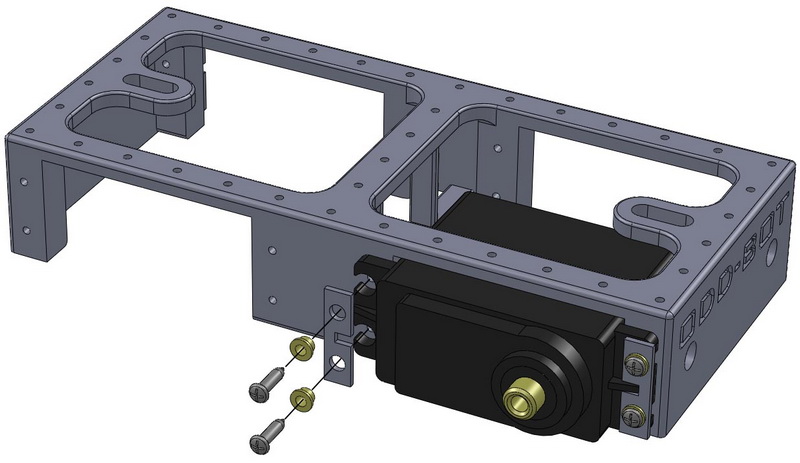
IMPORTANT NOTE: Use a marker pen to label your motors from 0 to 3, and also mark a number at the end of the motor wires near the connector. This will make it much easier to figure out which motor plugs in where later!
Step 5: Attach the assembled wheels to the motors using the screws provided with the motors.
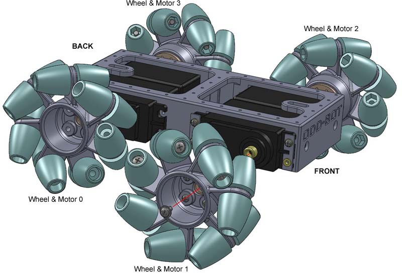
Take particular care that you screw on the wheels in the correct orientations, otherwise the OddBot will not go in the correct direction.
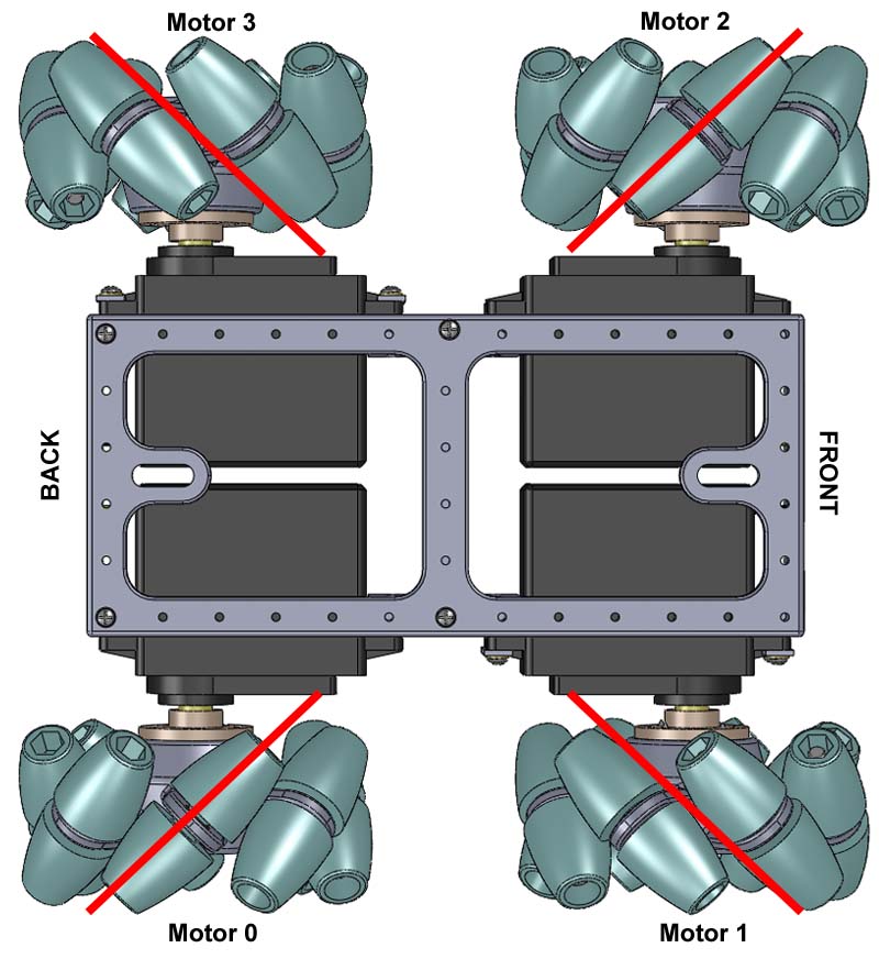
CONGRATULATIONS! You now have a little robot platform that you can use whatever micro-controller you prefer to make it smart. Lots of holes are provided on the chassis to make it easy to mount sensors, etc.
The instructions from this point on are for using an Infocast (Chumby) as the micro-controller, a Pololu Maestro 6 channel servo controller, and a whole bunch of AA batteries to power it. You also need a voltage regulator, such as the Satistronics LM2596, to regulate the power to the Infocast.
The Infocast 3.5" is a media display which makes a fantastic little computer for hacking projects. It includes WiFi, a touch-screen, and a whole bunch of other goodies, that make it useful. On E-Bay, you can, typically, buy them for between US$29 (if you are lucky) to US$69.
Before you jump to step 6, it is useful to load the OddBot software onto the Infocast, before you pull it apart, as it is much easier to setup while the touch-screen is active.
SETTING UP THE INFOCAST
- Activate your infocast by following the on-screen instructions. You will need a WiFi connection to do this.
- Enable SSHD on infocast by going to the secret screen on system info page: press "PI" symbol at top right of network address screen.
- Connect to the infocast using winscp. Network encryption/security on your wifi connection should be off. In WinSCP, type in the IP address of the Infocast (as given on the "system info" page of your Infocast), and use root as user name and no password.
- Download the OddBot software files and unzip them to a folder on your computer.
- Use WinSCP to Copy the python_chumby_2.7.1.tar.bz2 file, and the entire "oddbot" folder onto the /mnt/storage partition of the Chumby/Infocast.
- Also copy the rfs1 folder into the psp directory (the folder is empty, but is needed for a file that gets installed later)
- Unpack the python_chumby_2.7.1.tar.bz2 file as follows:
- Run the shell script install.sh.
- Then reboot / Power cycle the Chumby/Infocast.
From within WinSCP, start PuTTY (under command menu).
unpack the file with following commands:
cd /mnt/storage
tar xvjf python_chumby_2.7.1.tar.bz2
From within PuTTY:
cd /mnt/storage/oddbot
sh install.sh
Once it boots up, it should start up a WiFi access point called "oddbot". Connect to it using your Android Phone or even your PC.
You can now open up the Infocast, and disconnect all the connectors to the main circuit board, and disconnect the touchscreen. Also connect the smaller wifi circuit board into the main socket at the top of the main circuit board,
SETTING UP THE POLOLU MAESTRO SERVO CONTROLLER
Download and install the Maestro Control Centre from the Pololu website.
I n the The Pololu servo controller change the serial mode to USB dual port
Step 6: Attach the battery holder to the back of the chassis using four M2 x 8 self-tapping screws.
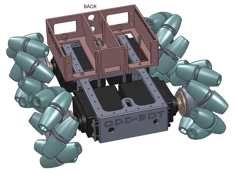
Step 7: Screw on the plastic frame that will allow the Infocast to clip onto the Oddbot using two M2 x 8 self-tapping screws.
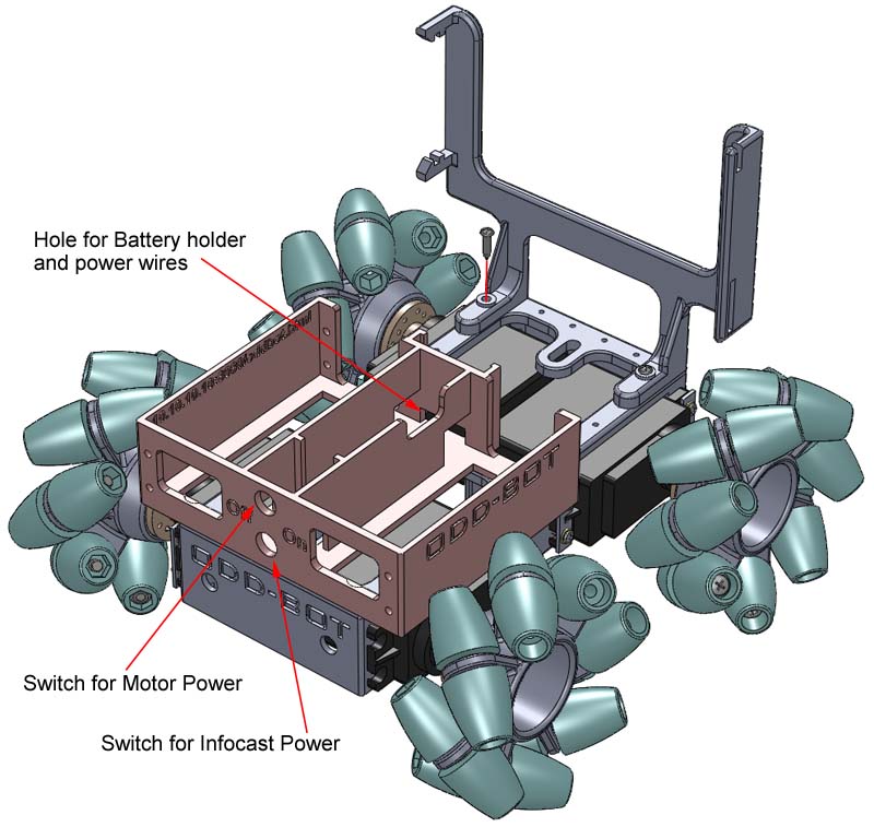
Step 8: Wire it all up. We use a separate circuit to power the motors to that to power the infocast. This is to prevent power surges from the motors affecting the Infocast.
Note that, in order for the OddBot to be tidy, the circuits need to be soldered while partially on the OddBot chassis as some of the wires go through holes in the plastic components, and can not be put though the holes after soldering.
Motor Power Circuit: This is the circuit to power up the Pololu Maestro 6 servo controller.
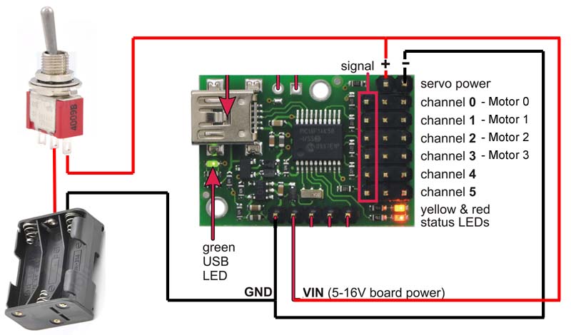
Though you can solder directly to the servo motor controller pins, we recommend against this. Rather use the proper connectors, as shown below, as it will make later service or modifications much easier. If you have any old computers lying around, you can usually recycle a few of the connectors form it to use in this project.

Infocast Power Circuit: This is the circuit to supply 5V (regulated by the Satistronics LM2596 voltage regulator) to the Infocast micro-controller.
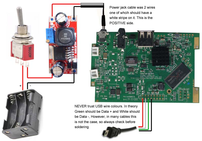
Be very careful that the Green and White wire from the USB cable are the correct way around. The Green "should" be Data +, but it's always worth double checking that it really is as many USB cables to not adhere to the convention.
TIP: The servo motors come with longer than necessary wires so, under the OddBot chassis you will see 2 pillars that can be used to wind up the excess wires. This will keep the top of your OddBot neat and tidy and give more space for other sensors.
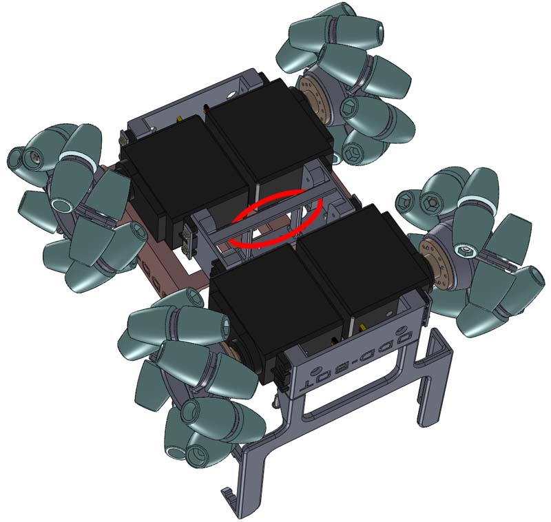
Step 9: Final assembly.
Plug the USB cable form the Infocast into the USB socket of the Pololu Maestro 6 servo controller. Plug the power jack, from the Infocast power circuit, into the Infocast, and the connectors from the Motor power circuit onto the Pololu servo controller. Connect the 4 motor cables to the Pololu servo controller. BE SURE TO OBSERVE ALL THE CONNECTORS ARE THE CORRECT WAY AROUND!
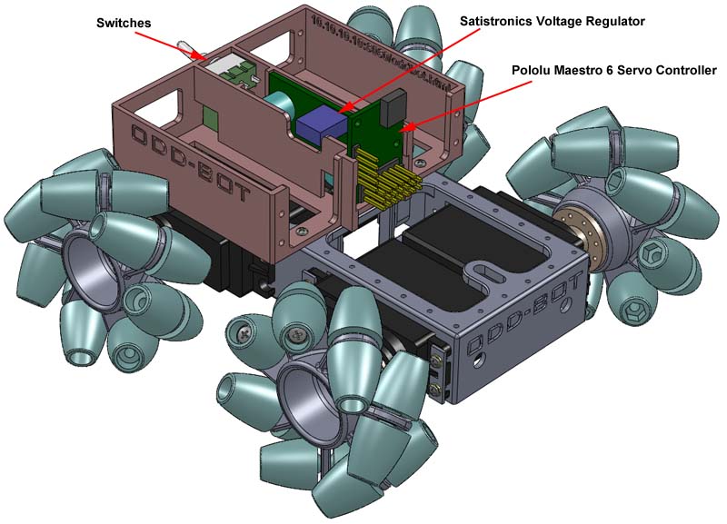
If you've done everything right, then your OddBot should look something like the one at the very top of this page.
Tuning the servos
When you run the OddBot, you may notice that some of the servos are spinning wihtout you doing anything. This means the servos need to be tuned into the 'neutral' position. Use a small flat screw driver and gently insert it into the holes shown in the picture below, until you find the small slot in the servo. Then gently turn the screw driver in one direction or the other until the servo stops.
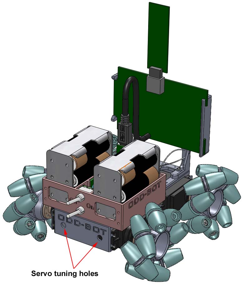
And now, the fun...
Switch on both switches on your OddBot. After about 45 seconds, the green LED on the WiFi card should start flashing. This means your WiFi network has been created.
On your iPad, iPhone, smart phone, or PC, go to your WiFi connections, and connect to the oddbot network.
Open your favorite web browser and go to the address:
http://10.10.10.10:8080/oddbot.html
This should open a webpage that looks something like this:
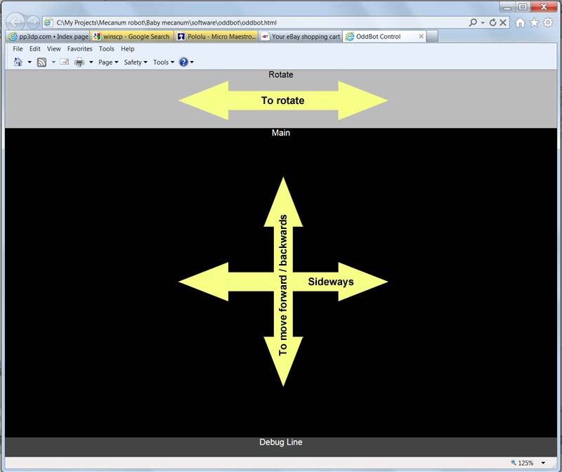
Start with your finger in the centre of the black area and drag your finger in the direction you want to go. as long as you keep your finger on the screen, the OddBot will continue moving. Lift your finger and the OddBot will stop. Use the grey bar at the top to rotate the OddBot like a tank.
该文章所属专题:3D打印
1;所有标注为智造资料网zl.fbzzw.cn的内容均为本站所有,版权均属本站所有,若您需要引用、转载,必须注明来源及原文链接即可,如涉及大面积转载,请来信告知,获取《授权协议》。
2;本网站图片,文字之类版权申明,因为网站可以由注册用户自行上传图片或文字,本网站无法鉴别所上传图片或文字的知识版权,如果侵犯,请及时通知我们,本网站将在第一时间及时删除,相关侵权责任均由相应上传用户自行承担。
内容投诉
智造资料网打造智能制造3D图纸下载,在线视频,软件下载,在线问答综合平台 » 3D打印全向轮式机器人步骤(英文)(图文教程)


